Building a Multiplayer Game with Node.js and Node-webkit: Tiles and Sprites
In the first part of this tutorial we have prepared a project structure and implemented all the tools we need to start making a client part of the game: graphics, controls and sound are all in place with ready to use resource management and local storage for temporary session-bound data. The next step is to implement our gameplay ideas using this simple tools.
As I said before I want to make something top-down, with tile-based levels and keyboard+mouse controls. I don’t want to make it too real-time and fast-paces because it takes too much effort to properly implement things like client-side prediction, lag compensation and such. This concepts deserve a (huge) separated article on its’ own. To make a game without digging into this concepts we need to make all controls a bit indirect. For example our movement mechanics can’t be WASD-based and should instead be more like RTS-style point-and-click “tactical” experience. With such controls it’s OK for player to wait several milliseconds while his command make it to the server and server respond with feedback events. We’ll talk more about such things in the next part of the tutorial.
For now let’s concentrate on implementing our levels’ and characters’ visuals keeping in mind the limitations described above.
Tiles and Coordinate System
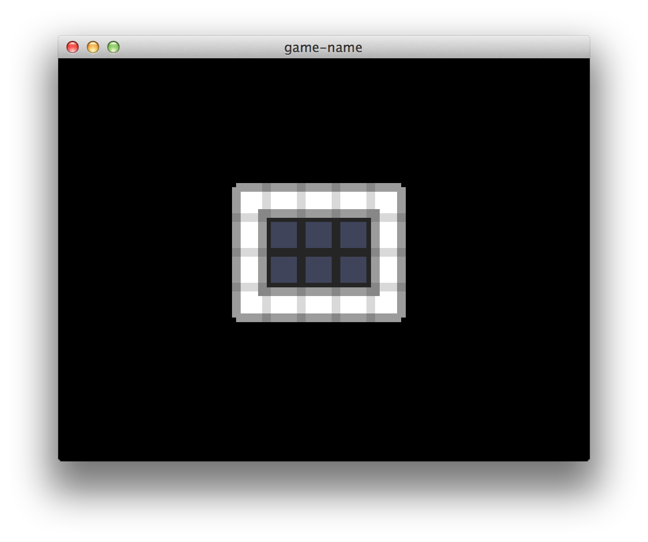
Levels in our game will be represented by matrices of square tiles. Below is a quick mock-up of what I mean. I am using Oryx’s lofi sci-fi sprite set for some of this. This sprites are not free and will not be included in the tutorial repository. If you have similar sprites that you are willing to share please let me know.
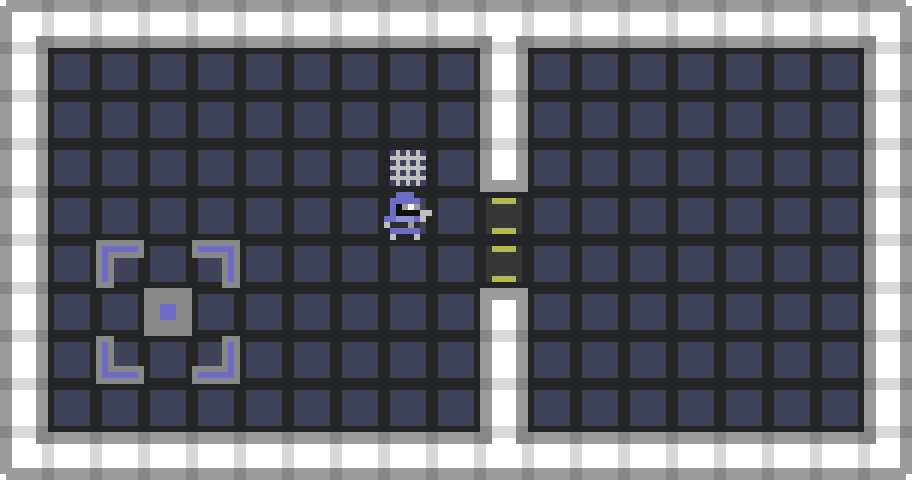
In the game I have in mind levels will be a bit bigger than one on the mock-up (at least like 10x bigger) and would not always fit the screen. So we need to implement a kind of coordinate system and “camera” concept defining origin of the game screen relative to some global level origin. It’s also always nice to make things independent of tile size. I want to be able to just say that the guy in the spacesuit are in the (8, 5) coordinates relative e.g. to the left bottom corner of the level (which is in (0, 0)) and don’t care about pixels until I want to actually draw him to the screen. Among other things it allows us to easily implement a concept of camera zoom (when user scaling the map trying to think about game events more strategically) and mini-map (an always-on-top widget showing an overview of the surrounding area).
Implementing Coodinate System and Camera with WebGL
If you are using plain 2D canvas instead of WebGL I suppose you already know what you are doing so just skip this part. For others I need to clarify how our newly designed coordinate system and camera could be implemented with WebGL.
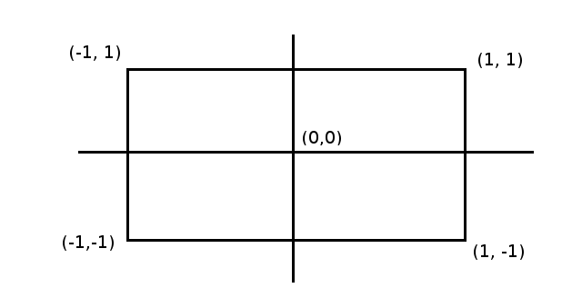
As you probably know WebGL (as any other OpenGL) knows nothing about coordinate systems. Instead it says that at the end of the day we need to specify positions in so-called “clip space coordinates”. Basically both X and Y clip coordinates must be inside [-1, 1] range. Everything outside this range will be “clipped-out” - discarded and invisible from the viewer. (0, 0) point is defined as a center of viewing area.
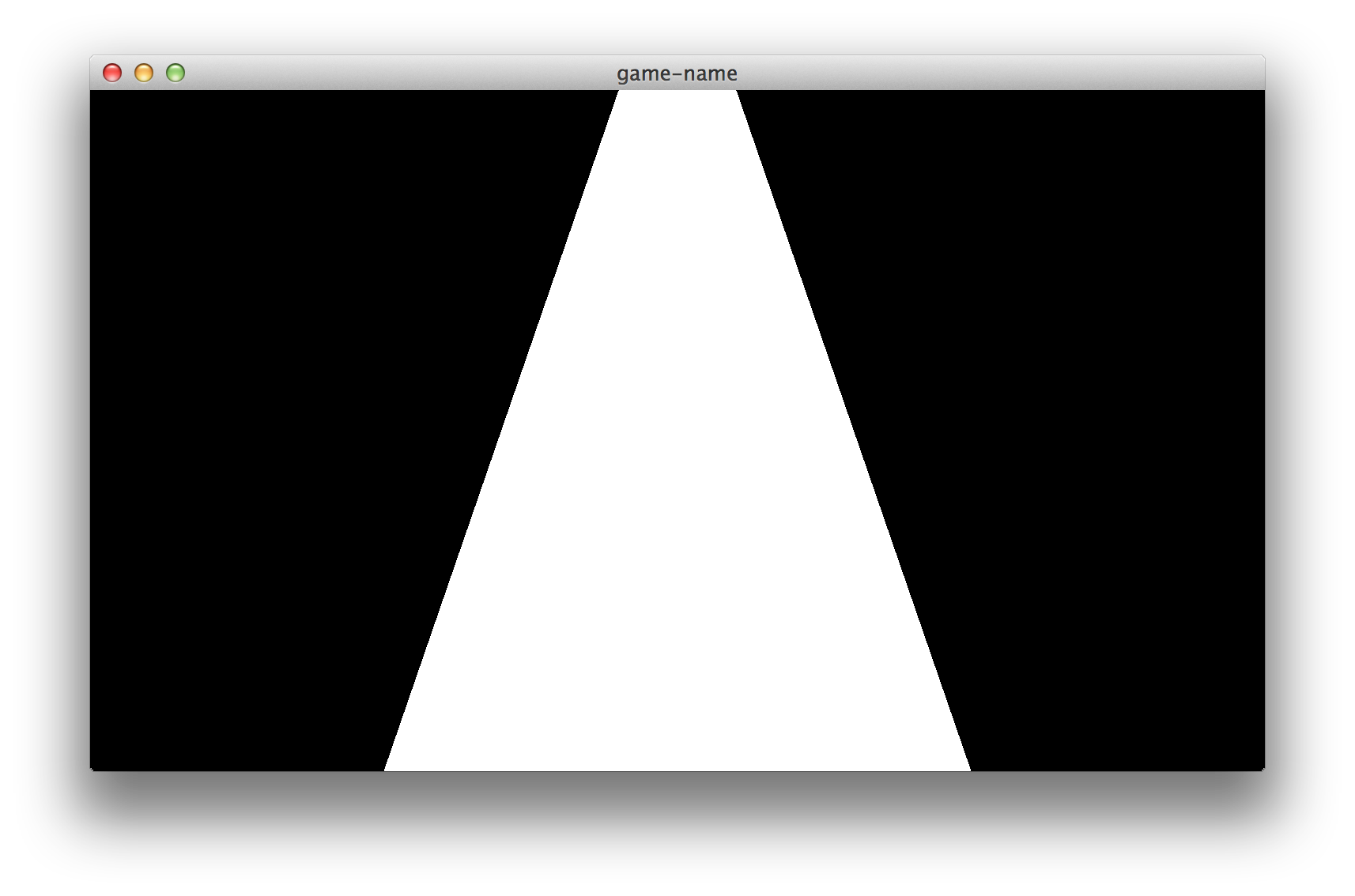
For example check out my “Hello Triangle” implementation here. On line 27 I am specifying positions of three vertices of my triangle. Like so:
1 | var vertices = [ |
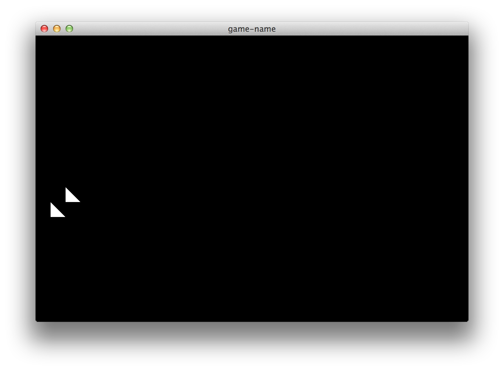
Experiment with this a bit. Try to put some vertices outside of [-1, 1] range on any direction and see what will happen. You should probably end up with something like this:
Parts of the triangle outside of the viewing area have been discarded! And that’s what we want in our game too. We want to perform a transformation to our tile-based coordinates in such a way that position of everything we want to see fall to the area of [-1, 1] and other staff be outside of it. For this purpose we need to define a matrix that we can multiply to all our vertices (defined in our tile-based coordinate system) to move them in our new window coordinate system - scaled by window size and tile size and translated to stick with our camera.
To create this matrix I suggest to use gl-matrix library. Like so:
1 | var glm = require("gl-matrix"); |
As you see I am creating an orthographic projection matrix first. It’s just to move from clip-space coordinate system to something close to window coordinates where one unit represents one pixel. This matrix actually changes only when user resizes the game window.
Then I am composing two matrices: one for scaling and one for translation (you need one more matrix to support rotation if you wish). This matrices could actually be recomputed only when user pan or zoom, but for simplicity let’s do this for every frame. Then I am multiplying them together effectively getting a combined zoom+move view transformation matrix (you need to read up on this if you don’t know why it works). Then I am multiplying projection matrix to view matrix getting the full transform that could be passed to shader.
With this setup and a bit of shader logic (e.g. gl_Position = view_projection * vec4(position, 1.0) we can easily draw triangles and other geometry snapped to invisible grid and scaled to match with it’s scale. Here is an example drawing. I defined two triangles: one in (0, 0) and another in (1, 1), shifted camera by (1, 7) and set a scale rate of 24 (in pixels per coordinate system “unit” - tile size):
You can also define keyboard shotcuts to play with scale and camera like so:
1 | $(frame.document).bind('keydown', "-", function () { |
Rendering Sprites
We define sprite as a tile-sized image located somewhere in our coordinate system. This includes map tiles themselves, game characters and objects (I assume that everything in our game will be of tile size or less) and some map-related GUI elements (like selection area highlighting). We want to implement an API allowing us to just specify what images we want to draw on a particular location without thinking to much about camera, scale and other stuff. We also want to be able to draw lots of sprites without affecting the framerate. For this purpose we’ll introduce a concept of spritesheet (also called a texture atlas).
Spritesheet is just an image containing all of our sprite images side-by-side. We can draw a particular sprite by just specifying coordinates of a part of the sheet containing sprite image. Here is an example of what I have in mind:
On this single image we have all images used to create a mock-up in the beginning of the post. We also have more images for “space marine” type because we have to provide him with movement animations for all supported directions. Red color here is just to visualize transparency - in actual spritesheet image I’ll use normal PNG transparency instead.
To actually draw sprites to the screen we’ll be creating a screen-aligned quad (using two triangles) for each sprite and mapping spritesheet image to it’s surface as a texture. The process is actually fairly straightforward. Firstly we need to load spritesheet image and create OpenGL texture object to hold it. Like so:
1 | function preloadSheet (url, clb) { |
Then we need to implement a transformation between high-level sprite concept (a tuple (x, y, z, tex_x, tex_y)) and actual geometry (triangle vertices). Here is a blunt implementation example. It uses just one vertex buffer to store position and texture data side-by-side.
1 | function tessellateSprite (sprite, buf, index) { |
As you see it’s quite simple because we just store positions in tile-based coordinate system. + 1.0 here actually means next tile. Texture locations are in “atlas-based” coordinate system that starts in the top left corner of the spritesheet and where + 1.0 means next sprite. Texture coordinate system is turned upside-down for the first glance but photoshop and similar tools often use this coordinate system and it’s always nice to match with your tools. Transformation from one coordinate system to another can be easily done in shaders:
1 | uniform mat4 projection; |
1 | uniform sampler2D sampler; |
In the fragment shader tex_ratio uniform defines a size of one sprite relative to the size of spritesheet image (in my case it’s 24.0 / 512.0). We could also use matrix to define atlas coordinate system but it looks like overkill for that simple sprites implementation. On the other hand we could use points to implement screen-aligned quads. It looks like a very nice optimization (6 times less data for one sprite) but there is one drawback when using them for anything except small particles: points get clipped by their centers so tiles near the edge of the screen will be flickering depending on the camera position and zoom level. This problem is solvable though so if your profiler shows you that you’re sending to much data to the GPU at least try this approach for yourself.
Speaking of the API design for our sprite render I like to separate the whole thing into three parts:
Spritedata structure to hold actual sprite parameters. In our case it’s just position, depth (we’ll talk about this later) and texture coordinates but for some games there may be more parameters here. For example you can add sprite opacity or overlay color.SpriteBufferclass to hold a bunch of related sprites together. For example if you have huge maps you want to separate tiles to several “chunks” and skip drawing chunks that can’t be seen with the current camera setup. Here I am usually also implementing a tessellation algorithm, vertex buffer operations and an attribute binding routine (just to hold knowledge about underlying buffer structure in only one class).SpriteRenderclass to hold actual rendering parameters (like shader program, texture, attribute locations etc) and perform batch rendering ofSpriteBuffers. So if all of your map chunks uses the same program and spritesheet you can bind program, set uniform values and bind the texture only once. Another nice thing to have this separated fromSpriteBufferis that you are able to draw the same buffer twice with different programs. E.g. draw map tiles to the screen and then draw the same tiles to the mini-map widget just using different texture and viewport.
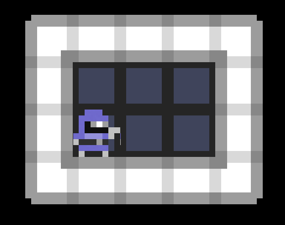
Here is a source code for this design and here is a nice screenshot with resulting rendering:
Solving “Texture Bleeding”
Texture bleeding is a nasty bug appearing when you position your geometry somewhere between screen pixels. Here is how it looks:
There are lots of hacks all over the internet trying to solve this issue but the most obvious way is to just snap everything to pixels. For now we have three sources of geometry locations:
- Sprite position
- Camera
- Scale
All we need is to keep integer scale and snap other values like so: snapped = ceil(original * scaleFactor) / scaleFactor. We can’t do pixel snap of tile positions because if we do we need to recalc them on every scale change. That’s too expensive. But tile positions can’t cause the issue if we use snapped scale and camera so we can just ignore them entirely.
If you really want to keep sub-pixel positioning capabilities (e.g. if you want to support camera rotation) you can try a common “half pixel correction” hack. Check out this popular gamedev.stackexchange answer providing an explanation of the technique. I can’t reproduce any bleeding when using this approach with this tutorial code but you should test it for yourself.
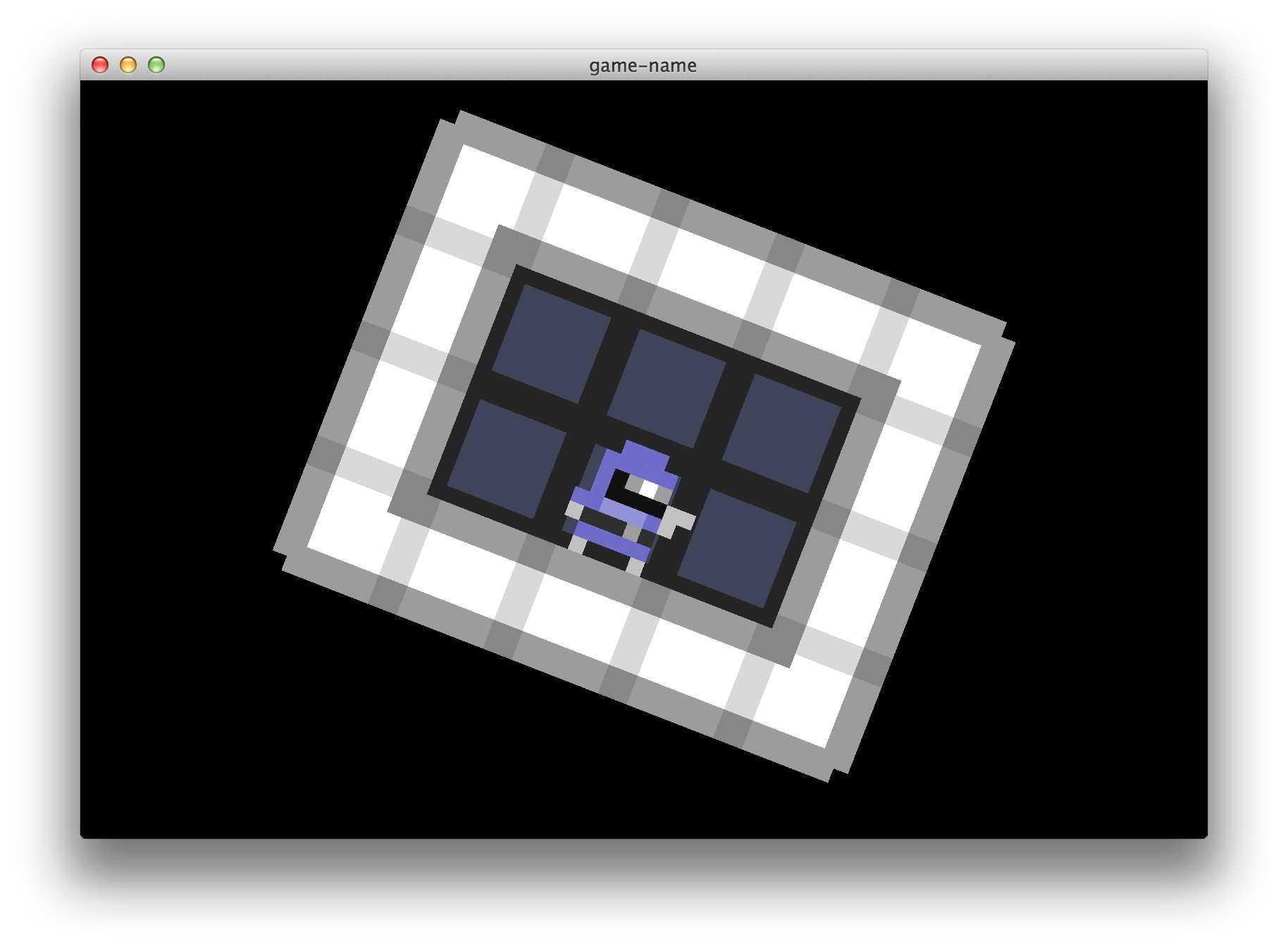
Here is a branch where I incorporate the technique. I also add Q and E shortcuts to rotate camera around the bottom left corner of the window and made all the camera transitions act on sub-pixel scale so you can test the solution properly (you can always use webkit console to set any values you like if the transition speed is too slow e.g. require("../render").setCamera([2.0, 2.0])).
Here is a picture of how it may look:
As you see it’s not pixel-perfect: character’s right arm looks a pixel thiner than it should. Another limitation is that you need to have all of your sprite sheets equal in sprite size, because equation of half_texel = 0.5 / sprite_size become a part of your vertex data.
The last approach I know (and will be using for this tutorial) unfortunately requires some additional data to be passed to fragment shader and used to compute fetch coordinates in more managed way. I call this “Fragment Shader Clamp-to-Edge Emulation”. The basic idea is to force fetch coordinates to always be inside a rectangle we want to map even if rasterizer says they should be on the very edge of it. It mirrors a behaviour of GL_CLAMP_TO_EDGE flag but works not only for the whole-image textures but also for texture atlases. Check out the implementation here. And here is a resulting screenshot:
As you see it renders everything nearly perfectly and also supports changing texture size in runtime. I haven’t used the technique in production yet so please let me know if you have any issues.
Smoothing Out Input
Our simple “shortcut” approach works just fine for things like changing current weapon, open menu etc. But to achieve smooth camera movements, zoom and rotation we need to somehow “animate” this values based on input. We need a sort of “game loop” implementation on the client that measures time passed between frames, captures input and uses some functions to change values appropriately.
Here is a snippet of how I commonly do this:
1 | var processInput = (function () { |
As you can see I only listen to keyboard events to remember what keys are down at the moment of the frame. Than each frame I just call handler functions for all keys that I know are down passing time delta to handle FPS changes gracefully.
Using Depth
Z coordinate value can be used to determine a depth position of our geometry. If you have web development background you can think of it like z-index value. To be able to use it exactly like z-index (where the value of e.g. 100 is the closest to the viewer and 0 is farthest) you need to define your orthographic projection as follows:
1 | glm.mat4.ortho(screenProjectionMatrix, 0, canvas.width, 0, canvas.height, -100, 1); |
For a sprite-based 2D game we also need to define a kind of standard of setting Z values for our sprites. As an example let’s agree on this:
- Everything acting as a floor should have Z of 10
- Everything lying on the floor should have Z of 11-20
- Characters should have Z of 21-30
- Walls, gates and other huge structures standing on the floor - 31-40
Using such a standard it is quite easy to keep everything in order. Don’t forget to gl.enable(gl.DEPTH_TEST) or OpenGL will just ignore your Z values entirely.
Check out the full source code for this part of tutorial. In the next part we’ll dive into networking and make our game actually respond to player controls. Stay in tune! UPD: part three is online.
BTW if you want to learn more about OpenGL and graphics programming in general I suggest you to read Learning Modern 3D Graphics Programming - a free ebook by Jason L. McKesson. It uses C and plain old desktop OpenGL but you’ll get used to it. On the other hand if you don’t want to dig into this concepts too much right now you can try to use a higher level library like pixi.js instead.